Your industrial machine just stopped detecting objects, throwing error codes like ‘Sensor Fault’ or ‘No Object Detected’. This guide walks you through diagnosing a failed proximity sensor switch, from a quick multimeter check to full replacement, using specific part numbers and real-world costs.
What’s Happening — Symptoms in Detail
Your machine just stopped working correctly. You likely see one of these symptoms:
- Error Code on Screen: Common codes include ‘Sensor Fault E002’, ‘Proximity Error’, or ‘No Object Detected’. The machine may refuse to start a cycle.
- Intermittent Triggering: The sensor works sometimes, then stops. You might see the machine’s indicator light flicker or stay on when no object is near.
- No Response: The sensor’s LED (if visible) is dark, even when a metal object is right in front of it. The machine acts as if the sensor isn’t there.
- False Triggering: The sensor stays ‘ON’ constantly, or triggers with nothing nearby. This causes the machine to jam or cycle incorrectly.
When does it happen?
- During Operation: Sudden failure mid-cycle, often after a jam or crash.
- On Startup: The machine boots up but immediately shows a sensor error.
- After a Crash: A heavy object hit the sensor, or the machine arm slammed into it.
- After Cleaning: Someone sprayed liquid or compressed air near the sensor, damaging it.
How does it progress?
- Slow Decline: The sensor becomes less sensitive over weeks. You have to bring objects closer for it to detect. Eventually, it stops working.
- Sudden Death: One moment it works, the next it’s dead. This often follows a power surge or physical impact.
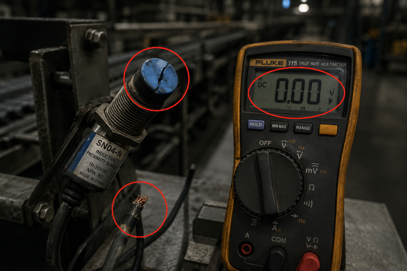
Real-world example: A conveyor line stops. The PLC screen shows ‘Zone 3 Sensor Fault’. The red LED on the SN04-N sensor is off. Even a steel wrench placed directly against its face does nothing. The line is down, and production is halted.
How to Diagnose the Problem Step by Step
Tools Needed: Digital Multimeter (set to DC voltage), Small flathead screwdriver (for terminal blocks), Test object (a steel bolt or screwdriver).
Beginner’s Quick Check (2 minutes):
- Power Check: Look at the sensor’s LED indicator. Normal: The LED is lit or flashes when an object is near. Abnormal: The LED is completely dark. Unplug the sensor’s connector and plug it back in. If still dark, the sensor likely has no power or is dead.
- Physical Damage: Inspect the sensor face. Normal: Smooth, clean plastic or metal face. Abnormal: Cracked, chipped, or melted face. If damaged, the sensor is broken.
- Cable Check: Wiggle the cable near the sensor and near the connector. Normal: No change in LED. Abnormal: The LED flickers or the machine’s error clears momentarily. This indicates a broken wire inside the insulation.
Detailed Diagnosis (10 minutes):
- Verify Power Supply: Set your multimeter to DC Volts (20V range). Place the red probe on the sensor’s Brown wire (V+) terminal and the black probe on the Blue wire (0V/GND) terminal. Normal: Reading between 10-30V DC (typical for industrial sensors). Abnormal: 0V means a blown fuse, bad power supply, or broken wire. If voltage is present, the sensor is getting power.
- Test Output (NPN type - most common): Set multimeter to DC Volts. Place red probe on the Black wire (Output) terminal, black probe on Blue wire (GND). With no object near the sensor: Normal: Reading is 0V. Abnormal: Reading is +V (e.g., 24V) — sensor is stuck ON. Now place your steel bolt directly against the sensor face: Normal: Reading jumps to +V (e.g., 24V). Abnormal: Reading stays at 0V — sensor is stuck OFF or dead.
- Test Output (PNP type): Same setup, but red probe on Black wire, black probe on Blue wire. Normal with no object: 0V. Normal with object: +V. Abnormal: No voltage change.
- Load Test: If the sensor switches voltage but the machine still errors, the sensor may be weak. Connect a small 24V relay coil or a 1kΩ resistor across the output and GND. If the relay clicks or the voltage drops under load, the sensor’s internal transistor is damaged.
If the sensor passes all voltage tests but the machine still errors, the problem is likely the PLC input module or wiring, not the sensor itself.
Why This Happens — Root Cause
Why do proximity sensors fail? These are solid-state devices, but they have specific failure modes.
- Power Supply Overvoltage: A voltage spike (e.g., from a nearby motor starting or a lightning strike) exceeds the sensor’s maximum rating (typically 30V DC). This blows the internal voltage regulator or output transistor. The sensor dies instantly.
- Physical Impact: The sensor is mounted on a moving part (like a robot arm or conveyor gate). A crash or jam crushes the sensor face, cracking the internal coil or damaging the IC. This is common on SN04-N sensors used in stop-gate applications.
- Short Circuit or Overload: The sensor’s output wire (Black) is accidentally shorted to +V or GND. This draws excessive current, burning out the output transistor. This happens if a wire gets pinched in a terminal block or a metal chip bridges the contacts.
- Moisture or Contamination: Water, coolant, or oil seeps into the sensor housing through a cracked case or unsealed connector. This causes internal corrosion and short circuits. Look for green corrosion on the terminal screws.
- Cable Fatigue: The sensor cable is flexed repeatedly (e.g., on a robot wrist). Over thousands of cycles, the copper strands inside break. The sensor loses power or output intermittently. This is a common failure on E3F-DS30C4 sensors on automated guided vehicles.
- Age and Thermal Stress: Over years, the internal potting compound can crack from thermal cycling. This allows vibration to break solder joints. The sensor may work when cold but fail when hot.
Specific Models and Known Issues:
- SN04-N: The plastic housing is brittle. A minor impact can crack the face. The LED indicator is unreliable—it may stay lit even if the output is dead.
- E3F-DS30C4: The M18 threaded barrel can corrode in wet environments. The cable entry is a common failure point—water wicks down the cable into the sensor.
- U-type Photoelectric Switch: The internal emitter and receiver can become misaligned after a shock. The ‘sensor blocked’ state may be permanent if the lens is dirty or scratched.
Can You Fix It Yourself?
Difficulty Level: 2 out of 5 (Easy)
Time Required: 15 to 30 minutes for a complete replacement.
Skill Level Needed:
- You must be comfortable using a small flathead screwdriver to loosen terminal block screws.
- No soldering required if using sensors with pre-wired cables.
- Ability to read a simple wiring diagram (Brown=+, Blue=-, Black=Output).
Risks and What Could Go Wrong:
- Wiring Mistake: Connecting the sensor to the wrong voltage (e.g., 120V AC) will instantly destroy the new sensor. Always verify the power supply voltage first.
- Short Circuit: Leaving a stray wire strand touching another terminal can blow the machine’s fuse or damage the PLC output card. Use a multimeter to check for shorts before powering on.
- Wrong Sensor Type: Installing an NPN sensor where a PNP is required (or vice versa) will cause the machine to see the opposite signal. The sensor may appear dead because the PLC input expects a different voltage level.
- Overtightening: Cracking the sensor’s plastic housing by over-tightening the mounting nut. Hand-tighten plus a quarter turn is enough.
Tools Required (Specifics):
- Digital Multimeter (any brand, set to DC Volts 20V range)
- Small flathead screwdriver (3mm blade for terminal blocks)
- Adjustable wrench or 22mm socket (for M18 sensor nuts)
- Test object (a clean steel bolt or screwdriver at least 10mm diameter)
Cost Breakdown — DIY vs Professional
DIY Cost (Parts):
- Part #1: 1PCS Proximity switch SN04-N metal de… — $0.61 (perfect for simple metal detection, 3-wire NPN, 10-30V DC, sensing distance 4mm).
- Part #2: E3F-DS30C4 Proximity Switch Photoelec… — $1.25 (M18 threaded barrel, 4-wire NPN+PNP, 30cm sensing distance, ideal for longer range).
- Part #3: Photoelectric Switch U-type Sensor 1m… — $0.95 (U-shaped slot sensor for counting or detecting thin objects, 5-24V DC).
- Total DIY Cost: $0.61 to $1.25 plus shipping (typically under $5).
Professional Repair Cost:
- Service Call Fee: $75 to $150 (just to show up).
- Labor: $50 to $100 per hour (minimum 1 hour).
- Part Markup: The same $1 sensor is billed at $15 to $30.
- Total Professional Cost: $140 to $280.
When to Skip DIY:
- If the sensor is inside a safety-rated circuit (e.g., light curtain or emergency stop). These require certified replacement parts and a safety validation after repair.
- If the machine is under warranty. Replacing a sensor yourself may void the warranty.
- If you are not confident in reading a wiring diagram or using a multimeter. A mistake could damage the PLC.
- If the sensor is potted into a custom assembly (e.g., a robotic gripper). Replacement may require disassembling the entire mechanism.
Verdict: For a standard SN04-N or E3F-DS30C4 sensor on a conveyor or simple machine, DIY is absolutely worth it. The part cost is under $2, and the repair takes 20 minutes. You save over $100.
Repair Process Overview
Step 1: Power Down and Lock Out
- Turn off the machine at the main disconnect.
- Lock out the power source (use a padlock or tag). Verify with a multimeter that the sensor’s power terminals show 0V AC/DC.
Step 2: Remove the Old Sensor
- Loosen the terminal block screws and remove the three wires (Brown, Blue, Black). Note the positions.
- Unscrew the mounting nut with a wrench. Pull the sensor out of its bracket.
- If the cable is routed through conduit, pull the cable out gently.
Step 3: Prepare the New Sensor
- Unpack your new sensor (e.g., SN04-N).
- If the cable is too long, cut it to length. Strip 5mm of insulation from the three wires (Brown, Blue, Black).
- Tin the wire ends with solder (optional, but prevents fraying).
Step 4: Mount the New Sensor
- Insert the sensor into the bracket.
- Tighten the mounting nut by hand, then give it a quarter turn with a wrench. Do not overtighten — plastic threads strip easily.
- Adjust the sensing distance: The sensor should be 80% of its rated distance from the target (e.g., for a 4mm sensor, place it 3.2mm from the target).
Step 5: Wire the New Sensor
- Connect the Brown wire to the +V (24V DC) terminal.
- Connect the Blue wire to the 0V (GND) terminal.
- Connect the Black wire to the Input (PLC input) terminal.
- Double-check each connection. A single strand crossing to another terminal will cause a short.
Step 6: Power Up and Test
- Remove the lockout and turn on the machine.
- Use your multimeter to verify power at the sensor (Brown to Blue: 24V DC).
- Place the test object near the sensor face. The sensor’s LED should light up. The machine’s error should clear.
- If the LED lights but the machine still errors, check the PLC input module. The sensor output (Black wire) should switch between 0V and 24V as you move the object.
Common Mistakes:
- Wrong Wire Colors: Some sensors use different color codes (e.g., Brown=NO, Blue=NC). Always check the datasheet.
- Reversing Polarity: Connecting Brown to GND and Blue to +V will destroy the sensor instantly.
- Mounting Too Far: The target must be within the sensor’s rated range. A 4mm sensor will not detect a target at 10mm.
- Metal Chips: If the sensor is mounted near metal chips (e.g., from machining), chips can stick to the face and cause false triggering. Use a non-metallic shield.
After the Repair — Testing & Verification
Immediate Verification (first 5 minutes):
- LED Test: The sensor’s LED should turn ON when a metal object is within its sensing range, and OFF when the object is removed. If the LED stays on constantly, the sensor may be mounted too close to metal (e.g., a steel bracket).
- Machine Test: Run the machine through one full cycle. The error code should not reappear. The machine should detect objects at the correct position.
- Multimeter Check: Measure the output voltage (Black to Blue) with no object: 0V. With object: +V. If the voltage is stuck at 12V (half supply), the sensor may be damaged or the wiring is wrong.
First Hour of Operation:
- Thermal Check: After 30 minutes, feel the sensor body. Normal: Slightly warm (ambient +5°C). Abnormal: Hot to the touch (above 60°C). This indicates a short circuit or overvoltage condition. Power down immediately and re-check wiring.
- False Triggering: Watch for the sensor triggering when no object is present. This can happen if the sensor is picking up vibration from a nearby motor (use a shielded cable) or if a metal chip has stuck to the face.
- Intermittent Failure: If the machine randomly stops with the same error, the sensor may have a loose connection. Gently wiggle the cable near the sensor and near the connector. If the error reappears, the cable is broken inside the insulation. Replace the sensor again, this time with a strain relief on the cable.
Long-Term Monitoring (first week):
- Corrosion Check: If the sensor is in a wet environment, inspect the cable entry point weekly for green corrosion. Apply dielectric grease to the connector pins.
- Alignment Check: Ensure the sensor has not been knocked out of alignment by vibration. The sensing distance should be verified with a feeler gauge.
- Data Logging: If the machine has a PLC, monitor the sensor’s on/off count. A sudden increase in cycle time may indicate the sensor is becoming slow or intermittent.
When to Call a Professional Again:
- If the new sensor fails within 24 hours, the root cause is likely external (e.g., overvoltage, short circuit, or physical impact). Do not keep replacing sensors. Have a technician check the power supply and wiring insulation.
- If the machine has multiple sensor failures, the PLC output card may be faulty. This requires advanced diagnostics beyond this guide.
Parts You’ll Need
Here are the parts that match this repair. Click the link to check the current price on AliExpress.
| Product | Price |
|---|---|
| 1PCS Proximity switch SN04-N metal de… | $0.61 |
| E3F-DS30C4 Proximity Switch Photoelec… | $1.25 |
| Photoelectric Switch U-type Sensor 1m… | $0.95 |
Prices and availability are subject to change on AliExpress.